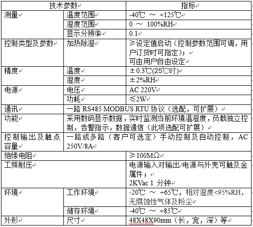
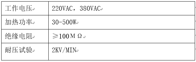
2. Technical parameters
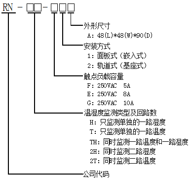
3, model definition
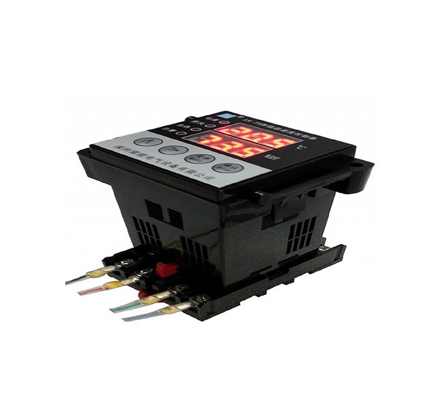
4. Installation method and terminal wiring diagram
The installation structure can be divided into embedded (panel type) and base type (rail type). Terminal wiring of corresponding structure

The picture is as follows:

Note: L1 means humidity load (connected to heater), L2 means temperature load (connected to fan).
When it is an embedded structure, the two spare terminals can be externally expanded to connect to the alarm output contact, which is optional for customers.
5, size chart
1. Dimensional drawing of embedded installation structure

2. The rail-type base is placed in the 35mm guide rail, and the installation structure size diagram is as follows:

3. Sensor installation and description:
The temperature and humidity sensor is integrated, using M3 screw fixed installation (hole center spacing 36mm, aperture Φ3.5mm) or 35mm rail installation. Shell size: 65X45X28.5 mm (length X width X height)
Shape and size of integrated sensor:

6. Product work and instructions
1. Manual control
Under normal working conditions, press and hold the right direction key for more than 3 seconds, the device enters the manual heating state, the heating indicator light is on, and the exhaust function is off; press the up direction key for more than 3 seconds, the device enters the manual exhaust state, and the indicator light is on , The heating function is turned off. For safety reasons, about half an hour after manual heating or exhaust is started, or when the corresponding button is touched again in manual mode, the corresponding manual heating or exhaust function will be turned off, and the device will enter the automatic measurement and control state.
2. Measurement
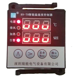
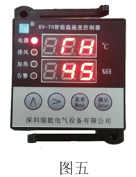
In the measurement state, the digital tube can simultaneously display the current test temperature and humidity values.
3. Control
Factory default setting:
Humidity is 85% to start the heater, 70% to turn off the heater (the return difference is 15%)
Start the heater at 5°C, turn off the heater at 15°C (return difference 10°C)
Start the fan at 45℃, turn off the fan at 37℃ (return difference 8℃)
When the humidity or temperature of the environment meets the pre-set working conditions, start the heater or fan, and the corresponding indicator lights at the same time. When the sensor fails and does not work according to the conditions, the corresponding alarm indicator lights, LED digital All lowercase letters u are displayed to indicate warning, as shown in the figure below:
Return difference: In the temperature and humidity control process, the difference between the temperature or humidity value when the execution component (heater or fan) starts working and the temperature or humidity value when it stops working is called the return difference value.
Details are as follows:
1) When the ambient temperature of the equipment is higher than the upper limit of the set temperature, the device starts the external cooling equipment (fan, etc.) to start exhausting air and cooling. At this time, the exhaust green light on the device panel will light up, indicating that the exhaust is activated. When the temperature drops (the upper limit temperature setting value minus the temperature return difference), the controller stops cooling.
2) When the ambient temperature of the device is lower than the lower limit of the set temperature, the device starts the external heating device (heater) to start heating, and the heating green light on the device panel will light up, indicating that the heating has started. When the temperature rises to (lower limit temperature setting value plus temperature return difference value), the controller stops heating up.
3) When the environmental humidity of the equipment exceeds the upper limit and the ambient temperature is high (when the temperature is greater than the upper limit temperature setting), the logic judgment adopts first cooling, starting the fan, etc., then heating, starting the heater, which is energy saving, and only one load is started at the same time Work until the temperature is normal and the humidity is lower than ((humidity setting value minus humidity return difference) value).
4) When the ambient humidity of the equipment exceeds the upper limit and the ambient temperature is low (less than the upper limit temperature setting value), heating and dehumidification are used until the humidity is below the target value (the humidity setting value minus the humidity return difference).
7, system setting mode
Enter/exit system setting mode:
Enter the system: Under normal circumstances, the controller is in the normal measurement and control working state. At this time, press the Enter key to enter the main menu, the upper column LED displays PSd, the lower column 000 flashes, and a password is required (you can also enter if the password is wrong Check the original set password, parameters, etc., but you cannot change the operation. The correct password must be used to change the parameter.) The password defaults to 001, see Figure 1 below:

The upper panel of the figure is from left to right, the first key is the up key (increment), the second key is the right key, press the right key to move to the third digit, press the up key and change to 001 and press the enter key to enter Three sub-menus, touch up, right arrow, the upper bar LEDs are displayed as T (including temperature setting), H (including humidity setting), OTH (including password and factory default parameters) as shown in the following figures 2, 3 and 4. Settings)

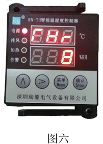
After entering the menu T by pressing the Enter key, the upper column displays TH (representing the upper temperature limit), and the lower column displays 45, which means the upper limit temperature parameter is 45 degrees Celsius. See Figure 5 below. In this interface, you can press the confirm button to enter the value flashing state, press Up key to increase the number, right key to select shift to modify the parameter, after the modification is completed, press confirm again to save (the following parameter modification method is the same as this step).
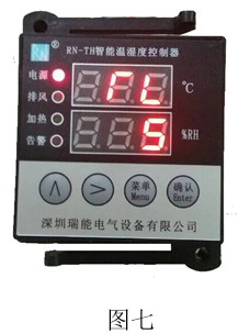
THr represents the setting of the hysteresis value of the upper temperature limit, the default is 8 degrees Celsius, see Figure 6 below.
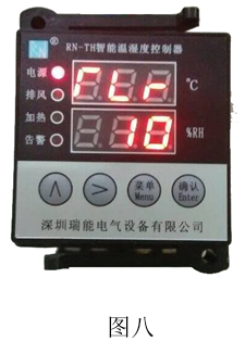
TL stands for the lower limit of temperature setting. The LED display in the lower column defaults to plus 5 degrees Celsius. The plus and minus sign can be set. The minus sign means minus degrees Celsius. See Figure 7 below.
TLr represents the temperature lower limit return difference setting, the default is 10 degrees Celsius, see Figure 8 below.
If you need to modify, press the confirm key to save after setting and press the menu key to return to the previous menu, press the up key or the right key to move to the H menu and enter, the Hd submenu, the lower LED displays 85, which means the upper limit of relative humidity is 85% (factory default value), see Figure 9 below, users can also modify it by themselves.

In the Hdr submenu, 15 is displayed on the bottom line, which represents a return difference of 15%. See Figure 10 below, which can be modified by users.

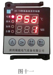
After setting the parameters, press confirm to save and press the menu key to return to the previous menu, press the up key or the right key to move to the OTH menu, press the confirm key to enter, where PSd stands for the password setting, the default is 001, see Figure 11 below, Users can modify by themselves.
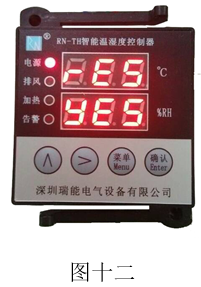
The rES menu stands for restoring the factory default settings. After you press the enter key to enter the menu, the number displayed on the bottom of the number “no” means to protect the custom settings and not restore the default settings. Press the up key to switch to the yES option, indicating that the factory settings need to be restored. Then select yES and press the enter key. See figure 12 below.
(Note: The total value of the temperature lower limit setting value plus the temperature return difference value must be less than the temperature upper limit setting value, and the total value of the temperature upper limit setting value minus its return difference value must be greater than the temperature lower limit setting value, otherwise set Invalid, unable to save the set data).
Exit the system: After returning to the option sub-menu, press the Menu button to exit the system setting mode and return to the normal working state. If you do not operate the button in the menu setting mode, it will automatically return to the normal working state after 1 minute. The parameters that are in the parameter modification state without pressing the confirm button will not be saved.
8. Precautions for use
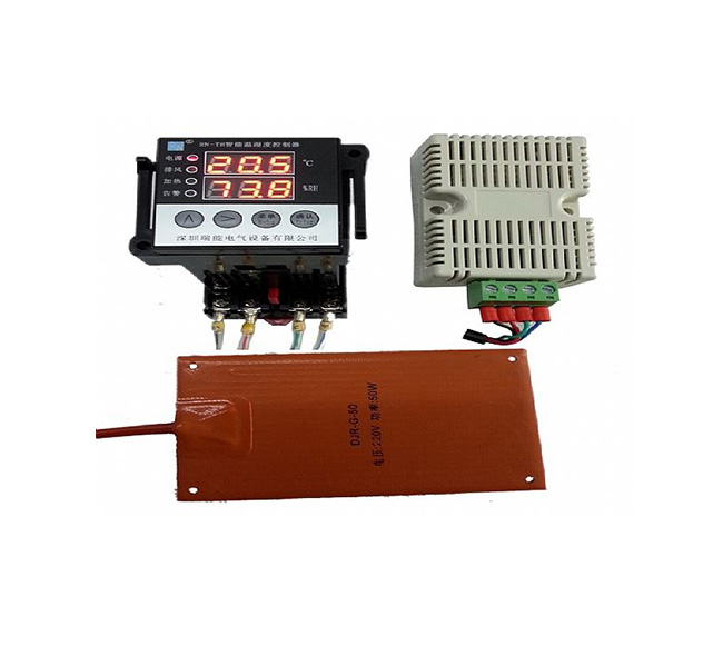
1. Each product includes a kit: 1 main device, 1 sensor, 1 manual
2. On the premise of carefully reading the instruction manual, make sure that your wiring is correct. Do not connect the wiring when the power is on, and it is not allowed to connect to overloaded actuators.
3. The signal line should be as short as possible. If a longer signal line is required, a shielded line should be used, and the shielding layer should be connected to the ground. Avoid equipment lines with strong interference as much as possible, and cannot be installed outdoors without protection.
4. Test humidity monitoring unit: In the automatic state, you can use a humidity generator or breathe in your mouth, approach the sensor for about 5 seconds, the indicator light on the monitor will light up, and the load will start working; stay away from water vapor, the indicator light will go out, the load will stop working, and the surface humidity sensor will work normal. In the manual state, the humidity indicator on the monitor lights up and the load starts to work.
5. Test temperature control function: In the automatic state, place the sensor in the temperature control test box to make the temperature in the test box reach the corresponding starting point temperature, or manually set the temperature upper limit parameter lower than the current room temperature or manually set the temperature lower limit parameter When the room temperature is higher than the current room temperature, the exhaust indicator light on the panel of the device is on or the heating indicator light is on, and the corresponding load starts to work; when the temperature rises (exceeding the return difference point), the cooling type is when the temperature decreases (over the return difference point), The indicator light is off and the load stops working, indicating that the temperature control function is normal.
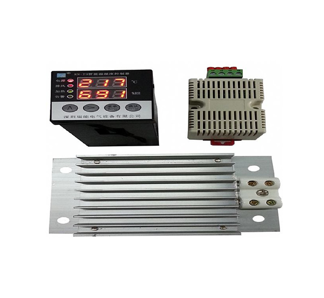
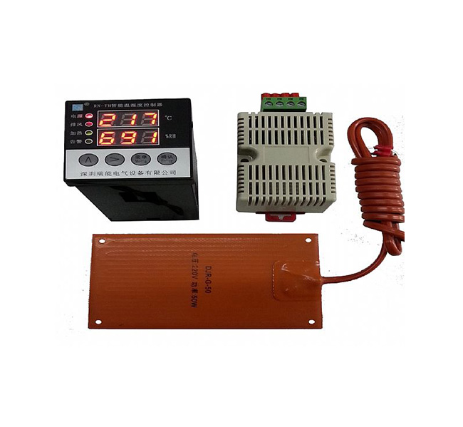
9, supporting load
We recommend to use: AC220V/50HZ
1. Electric heater: one is DJR type (aluminum alloy type), the other is DJB type (silicone rubber type), power 50W, 75W, 100W, 150W, 200W, 300W.
2. The fan, power, and volume can be customized according to your needs.
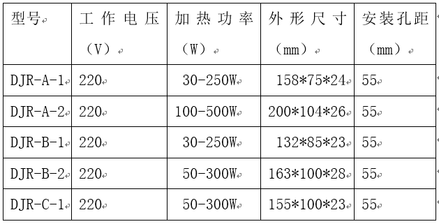
Part of the technical indicators of the heater
Heater selection table
10. Technology and Service
1. After receiving the product, the user will verify the product accessories. This product includes: temperature and humidity controller, temperature and humidity sensor (configurable according to customer requirements), instruction manual, etc.
2. This product provides a one-year warranty service from the day the product is sold.
3. If there is a problem during the use of this product, please do not disassemble or repair the product by yourself. Please contact our company in time, and solve the problem you encounter under the guidance of the technician.
4. If the function does not meet your requirements, please call, our company can customize the functions you need for you
11. Product order
The user must indicate the following items in the order form according to their needs:
1. Product model, quantity, and humidity sensor lead length (standard configuration 2.5 meters);
2. Product installation method, drive load power;
3. Receiving unit, consignee, address, zip code, etc.;
4. Freight mode: mail, railway express or other methods;
5. Items should be filled in when issuing a VAT invoice.

 Language