1 Overview
When ferromagnetic resonance occurs in the power system, it often causes the voltage transformer to burn out or explode, causing vicious accidents. To this end, the traditional solution is to connect bulbs or resistors in series on the open delta winding of the voltage transformer for attenuation. This method cannot solve the problem fundamentally, and its effect is extremely insignificant. Later, an analog harmonic elimination device appeared. Because it is not intelligent, it not only often malfunctions when the arc is grounded, but also can only eliminate the ferromagnetic resonance of a certain frequency, which has not been promoted and applied.
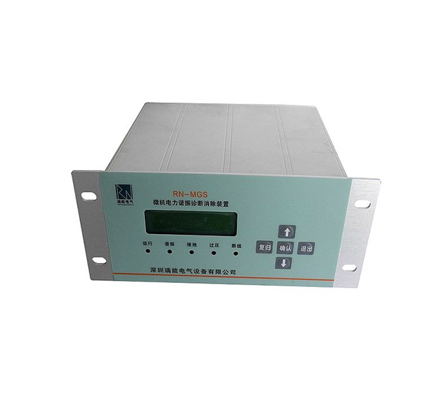
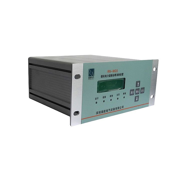
The JF-MGS microcomputer power resonance diagnosis elimination device developed by our company using high-performance 16-bit single-chip microcomputer and intelligent software technology can diagnose ferromagnetic resonance, and can also distinguish between overvoltage, ferromagnetic resonance, and PT high voltage Side disconnection, PT low-voltage side disconnection, single-phase grounding and other fault types; for ferromagnetic resonance of various frequencies, it can quickly eliminate and display relevant information. For overvoltage, ferromagnetic resonance, single-phase grounding and PT disconnection, etc., it can alarm, record and display. This device has been proved by large-scale enterprises such as electric power, metallurgy, coal, petroleum, chemical industry, etc., that the device has superior performance and is safe and reliable to use.
2 Features
2.1 No need to set and debug, and maintenance is small.
2.1 Automatically display and record the time and related parameters (amplitude and frequency) of overvoltage, ferromagnetic resonance, single-phase grounding, PT high-voltage side disconnection, and PT low-voltage side disconnection.
2.1 It can distinguish between overvoltage, ferromagnetic resonance, single-phase grounding, PT high-voltage side disconnection, and PT low-voltage side disconnection.
2.1 It can provide a comprehensive alarm signal, which can automatically display or record the time of failure and related parameters.
2.1 It is suitable for various voltage levels of the distribution network and various characteristic resonance frequencies (1/3 frequency, 1/2 frequency, power frequency, 3 times frequency), and has a wide range of applications.
2.1 Accurate diagnosis, rapid and thorough elimination of resonance.
2.1 Five fault information can be stored, recalled and displayed.
2.1 With RS-232 or RS-485 communication function, the communication protocol is CDT protocol.
2.1 With printing function (only MGS-XPXX series have this function).
2.1 There are 4 alarm node signal outputs, which can distinguish resonance, grounding, overvoltage, and disconnection.
3 Technical specifications
3.1 Working power supply: AC/DC 220V (-20% ~ +10%); Note: Type A working power supply: DC 110V (-20% ~ +10%); power consumption ≤10W.
3.2 Ambient temperature: -10℃ ~ +55℃.
3.3 Relative humidity: less than 90%.
3.4 Resonant frequency applies:
1/3 frequency division 1/2 frequency division power frequency 3 times frequency
3.5 Alarm relay contact capacity: DC 30V/1A; AC 250V/1A.
4 Model and version
4.1 Model meaning
4.2 版本含义
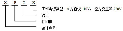
For example: MGS-1PT working power supply is AC/DC 220V, with printer and communication
MGS-1PTA working power supply is DC 110V, with printer and communication
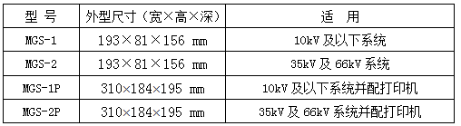
5 Model and function comparison table
6 The main difference with similar devices
6.1 This device has strong anti-interference ability and high data collection accuracy.
6.2 The central processor of this device uses a high-performance 16-bit single-chip microcomputer, which has fast calculation speed and strong control ability; it can distinguish between overvoltage, ferromagnetic resonance, single-phase grounding, and PT high-voltage side disconnection and PT low-voltage side disconnection.
6.3 This device can automatically display and record various failure times and related parameters, and provide data for on-site analysis.
6.4 The device can store five fault information, recall and display it.
6.5 This device adopts plug-in structure, which is simple and convenient to maintain.
6.6 This device uses a large-screen Chinese character LCD display, and the stored information will not be lost after the device is powered off.
7 Principle of the device
The central processing unit of this device uses a high-performance 16-bit single-chip microcomputer to cyclically detect the voltage of the PT open delta winding (ie: zero sequence voltage) and the three-phase voltage of the system. Under normal operating conditions, the voltage of the PT open delta winding is zero, and the high-power harmonic elimination components in the device are in a blocking state, which has no effect on the system.
When the system is in a fault working condition, the device analyzes and calculates the data collected by the open delta voltage of the voltage transformer and the three-phase voltage of the system to diagnose the current working condition. If it is a ferromagnetic resonance of a certain frequency, turn on the resonance elimination circuit to make the ferromagnetic resonance disappear quickly under strong damping, and give instructions at the same time. After the ferromagnetic resonance is eliminated, the device will record and store accordingly, and automatically display the time and related parameters (amplitude and frequency); if it is overvoltage, single-phase grounding or PT disconnection, the device will give instructions and alarms, which can automatically Record fault information.
8 Device software composition
The software of this device is mainly composed of sampling program, data processing program, fault processing program, display program, etc. As shown in Figure 5-1.
9 Device hardware configuration
The hardware of this device consists of the following components:
9.1 Output board
Adopt module power supply, output DC+5V, DC+24V; place high-power harmonic elimination components, comprehensive alarm relay; four-way PT and signal conditioning circuit.
9.2 Motherboard
High-performance 16-bit microcomputer chip: fast calculation speed, strong control ability, reliable operation, hardware watchdog to prevent crashes.
9.3 Display board
Use 122×32 LCD and LED to display and indicate various information.

Figure 5-1 Program block diagram
10 Device instructions
10.1 Button
The front panel of the device adopts plastic film veneer and touch buttons. The functions of the five buttons are defined as follows:
"Move up" key: When selecting a menu, move the cursor up; when changing the time, the value increases by 1;
"Move down" key: When selecting a menu, move the cursor down;
"Exit" key: Exit function;
"Confirm" key: Select to confirm;
"Reset" button: Manually reset the alarm signal (LED and signal relay).
10.2 Indicator light
The indicator lamp is used to indicate the running status and fault information of the device. The five signal indicators are defined as follows:
"Run" light: When the device is running, the "Run" light flashes green;
"Resonance" lamp: When resonance occurs, the "resonance" lamp glows red and flat;
"Grounding" light: When single-phase grounding, the "grounding" light will glow red and flat until the signal is reset;
"Overvoltage" light: When an overvoltage occurs, the "overvoltage" light glows red and flat until the signal is reset;
"Disconnected" light: When the PT is disconnected (high-voltage side and low-voltage side), the "disconnected" light will glow red and flat until the signal is reset;
10.3 Operating instructions
10.3.1 LCD display content when power on
When the device is powered on, the start screen of the device is displayed on the LCD, and the LCD backlight is lit (see Figure 10-1). The figure shows the device model and name in sequence.
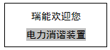
Figure 10-1
10.3.2 Run the main menu interface
After turning on the power, do not press any key, the system automatically enters the operating mode, the LCD screen (Figure 10-2). In any interface, if you do not press the key, the device will automatically turn off the screen in about 5 minutes. When the screen is off, press any key to turn on the backlight.

Figure 10-2
Note: The shaded area of 1 in the 10-2 screen is the cursor position. Use the "up" and "down" keys to change the cursor position and select five first-level menus with different functions.
The functions and operation methods of each sub-menu of the running main menu are introduced as follows:
"1. Device Management"
After the cursor moves to the first level menu of "device management", press the "OK" key to enter the second level menu under this menu, you can clear records, modify the clock, alarm configuration, parameter settings (see Figure 10-3), through " Move up" and "Move down" key to select the corresponding sub-menu function, press "Enter" key to enter the next menu. At this time, if you press the "Exit" key, you will return to the previous menu. The operation method of each level of menu is introduced as follows:

Figure 10-3
1) Clear records
After selecting the clear record submenu, press the "OK" key to clear the event record. After clearing, it will automatically return to the previous menu.
2) Modify the clock
After selecting the time modification sub-menu, enter the menu screen (Figure 10-4). Use the "move down" key to select different digits of the clock, use the "move up" key to modify the selected digit, and press the "confirm" key to confirm the modification and automatically return to the previous menu.

Figure 10-4
3) Alarm configuration
You can press the "move up" and "move down" buttons to move the cursor to select the item to be modified, and then press the "confirm" key to modify the selected item, and press the "confirm" key to make the alarm return state in "cast" Switch between and "Exit" (Figure 10-5). After modifying an item, press the "up" and "down" keys to select the next item to be modified. After modification, press "Exit" to return to the previous menu.
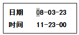
Figure 10-5
4) Parameter setting
After selecting the parameter setting submenu, enter the menu screen (Figure 10-6). Use the "move down" key to select the digits with different parameters, use the "move up" key to modify the selected digit, and press the "confirm" key to confirm the modification and automatically return to the previous menu. (Note: The baud rate can be selected in 1200, 2400, 4800, 9600, and the source station and destination station are displayed in hexadecimal system)
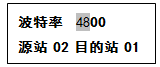
Figure 10-6
5) Exit "Device Management"
After modifying the parameters, press the "Exit" key, the LCD screen displays prompt information (Figure 10-7), and then returns to the previous menu.
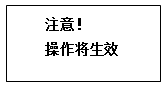
Figure 10-7
"2. Event Record"
After the cursor is moved to the "Event Record" menu, press the "Enter" key to enter this submenu (as shown in Figure 10-8), and you can view the previous failure reports. The number of fault reports ranges from 1 to 5, with number 1 being the oldest report, and number 5 being the latest report. Use the "move up" and "move down" keys to switch between reports; the first line of the LCD screen displays the serial number and type of the fault; the second line displays the time and value of the fault (open delta voltage). When the viewing is over, press "Exit" to return to the previous main menu.
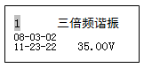
Figure 10-8
If there is no event record, it will display "No record temporarily" (Figure 10-9).
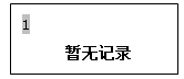
Figure 10-9
"3. System Clock"
After entering the "System Clock" menu, the system time of the device will be displayed, as shown in Figure 10-10. When the viewing is over, press "Exit" to return to the previous menu.
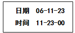
Figure 10-10
"4. Version Information"
After entering the "Version Information" submenu, the version information of the device will be displayed, as shown in Figure 10-11. Press the "Exit" key to return to the previous menu.
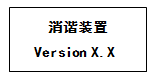
Figure 10-11
10.3.3 Alarm information display
When the system fails, the LCD displays the current fault information, the fault indicator on the panel lights up, and the alarm relay contacts are closed. After a fault occurs, press the "Exit" button, and the LCD will return to the main menu from the fault menu; after pressing the "Reset" button, the fault indicator and alarm relay will be reset; if the "Reset" button is not pressed, the fault indicator and alarm The relay will automatically reset after 2 minutes.
10.4 Test method of the whole machine
The experiment wiring diagram is as follows (take the power frequency voltage experiment as an example).

a) Single-phase grounding instructions and experimental methods
Input the power frequency between 30V and 120V to the signal input terminal "Uo, Un" of the device (time greater than 3 seconds), input 100V voltage for any two phases of A, B, and C, the positive sequence phase difference is 60 degrees, and the other Phase input zero, at this time, accompanied by the light bulb flashing once, the "grounding" indicator light is on, alarms, and fault information is displayed. When the "Uo, Un" terminal input signal is less than 30V, the device will not operate.
b) PT disconnection indication and experimental method
1. High-voltage side disconnection: Input the power frequency between 30V and 120V to the signal input terminal "Uo, Un" of the device (for more than 3 seconds), and input 57.7V voltage for any two phases of A, B, C, positive The sequence phase difference is 120 degrees, and the other phase inputs zero. At this time, with the light bulb flashing once, the "disconnected" indicator light will be on and alarm, and the PT high-voltage side disconnection fault information will be displayed.
2. Low-voltage side disconnection: Input a voltage below the power frequency start value (the factory default of the device is 30V) to the device signal input terminal "Uo, Un". As long as one of the three phases A, B, and C is input zero, "disconnect ”The indicator light is on and alarms, showing the fault information of the PT low-voltage side disconnection. (Due to the above situation, the device is powered on before the system is put into operation, the device reports that the PT low-voltage side is disconnected, the system is put into operation, and the alarm disappears after the PT is running normally)
c) Ferromagnetic resonance indication and experimental method
When the input signal terminal "Uo, Un" input a voltage above 30V for a short time (within 3 seconds), and quickly remove the voltage, at this time, with the light bulb flashing once, the "resonance" indicator light will be on, alarm, and the fault information will be displayed (that is, when When the system resonates, the zero-sequence voltage is relatively high. After the resonance is eliminated, the system returns to normal, and the zero-sequence voltage drops quickly).
d) Overvoltage indication and experimental method
When the input signal terminal "Uo, Un" is connected to a voltage above 120V (for more than 3 seconds), the light bulb flashes once, the "overvoltage" indicator light is on, an alarm, and the fault information is displayed (that is, when an overvoltage fault occurs in the system) After the resonance elimination, the overvoltage still exists and the system does not return to normal. At this time, the system failure should be eliminated as soon as possible to avoid loss).
11 Installation instructions
11.1 Overall dimensions and installation opening dimensions
11.1.1 MGS-1 and MGS-2 (Outline: 193×81×156mm; Opening: 163×82mm)
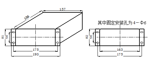
MGS-1 and MGS-2 appearance MGS-1 and MGS-2 outline installation cutout diagram
11.1.2 MGS-1P and MGS-2P (shape: 310×184×195mm; opening: 267×180mm)
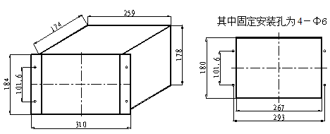
Outline drawing of MGS-1P and MGS-2P MGS-1P and MGS-2P installation cutout diagram
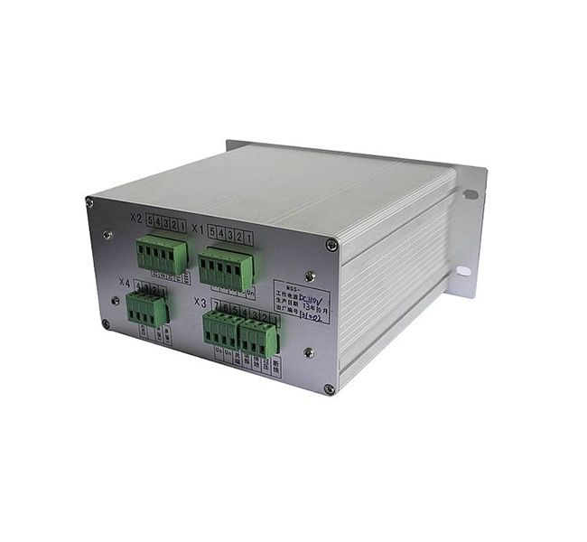
11.2 Terminal position diagram and description of each terminal
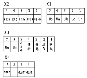
The description of each terminal is as follows:
X1:
1: Voltage common terminal Un.
2: Phase voltage Uc input terminal.
3: Phase voltage Ub input terminal.
4: Phase voltage Ua input terminal.
5: Open triangle Uo input terminal (for measurement).
X2:
1: R485B
2: R485A
3: T232 communication sender
4: GND
5: R232 communication receiver
X3:
1: Disconnection alarm relay output node.
2: Overvoltage alarm relay output node.
3: Grounding alarm relay output node.
4: Resonance alarm relay output node.
5: Alarm relay output common node.
6: Open triangle Un input (for harmonic elimination).
7: Open triangle Uo input terminal (for harmonic elimination).
X4:
1: Device power input AC/DC (L/+).
2: Device power input AC/DC (N/-).
3: Not used.
4: FGND shielding ground.
12 Fault diagnosis and error handling
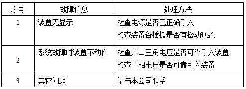
If you encounter a problem that you cannot solve by yourself, please contact our company so that it can be handled promptly and properly without affecting your normal use.
13 matters needing attention
13.1 To ensure the normal use of the device, please fix the case and connect the external wiring according to the above diagram, and focus on checking whether the positive and negative polarity of the DC working power supply for the device is correct, and whether the wiring of each signal circuit is reliable. After the above confirmation is correct, power on the device. For operation and usage, please read the aforementioned device instructions in detail.
13.2 The company’s products will be repaired free of charge if there is a quality problem within two years after the product is sold, and the product will be repaired for life. If the two-year period is exceeded, the repair of the device will be charged an appropriate amount of cost.
13.3 The normal working power supply of this product is AC/DC 220V. If other levels of power supply are required, please declare when ordering.
13.4 The storage temperature of the packaged products during transportation is -25℃~+55℃, and the relative humidity is not more than 95%.
13.5 The packaged products should be stored indoors at -10℃~+40℃, the relative humidity is not more than 80%, and the surrounding air does not contain corrosive, fire and explosive substances.
13.6 This product does not require on-site debugging. Please read the instruction manual for matters such as use and operation.
13.7 After opening the outer packaging of the new device, please carefully check the product packing list. If you find that the actual product does not match the list, please contact our company in time to avoid affecting your use.
13.8 The configuration in the manual is subject to change without notice, and the accompanying manual shall prevail.

 Language